DamageTC3D
Re: DamageTC3D
Probably I did not explain it well.
The characteristic length of the specimen is the length they used for computing the strain. Typically they place LVDTs, and they measure the relative displacement between them, dividing it by the distance between the LVDT's ends.
Typically it is a fraction of the full height of the specimen: Also, you should fix Ux and Uy also on the top face.
Alternatively, if you want to be more precise, you should use contact with the friction coefficient of concrete-to-steel.
The characteristic length of the specimen is the length they used for computing the strain. Typically they place LVDTs, and they measure the relative displacement between them, dividing it by the distance between the LVDT's ends.
Typically it is a fraction of the full height of the specimen: Also, you should fix Ux and Uy also on the top face.
Alternatively, if you want to be more precise, you should use contact with the friction coefficient of concrete-to-steel.
Re: DamageTC3D
Thanks for your clarification. The Gc value I estimated from the reference is 17.3 N/mm (fc=34.5Mpa), but the results of my model are very different from the results of the stress-strain curve obtained from the "material test", is this the reason for my model?
- Attachments
-
- Gc=17.3.png (27.56 KiB) Viewed 4705 times
Re: DamageTC3D
Is the background curve (in the monitor) the stress-strain curve from the experimental results?
If yes, could you provide some information about how they computed the strain from the displacement? More specifically, I need the distance between the LVDTs the used to measure the strain
Re: DamageTC3D
Sorry, I may not have been clear before. Due to the lack of test data. I want to simply test if the concrete parameters are correct. The background curve is the data obtained according to "Material Test" by inputting some parameter values (fc0, fcp, fcr, gc). The specific fracture energy (gc) is calculated by the classical compression full curve model (China code GB 50010-2010).
The fracture energy (Gc=(fc/ft)^2/Gt=17.3) is calculated according to your recommended method (CEB-FIB mode code).
The scale factor calculation process in monitor:
X Axis: dispalcement(set 3)/specimen height(300 mm)=dispalcement(set 3)*0.0033
Y Axis: reaction force (set 2) / area of bottom surface = reaction force (set 2) * 5.659e-05
The fracture energy (Gc=(fc/ft)^2/Gt=17.3) is calculated according to your recommended method (CEB-FIB mode code).
The scale factor calculation process in monitor:
X Axis: dispalcement(set 3)/specimen height(300 mm)=dispalcement(set 3)*0.0033
Y Axis: reaction force (set 2) / area of bottom surface = reaction force (set 2) * 5.659e-05
- Attachments
-
- Material Test.png (2.04 MiB) Viewed 4688 times
-
- fracture energy.png (3.75 KiB) Viewed 4688 times
-
- scale factor.png (3.62 MiB) Viewed 4688 times
Re: DamageTC3D
Ok, so if the China code gives you gc = 0.176, assuming lch_spec = 300 (even though it might be lower, you should check the distance between the LVDTs they used to compute strain from displacement), your Gc = 52.8.Sorry, I may not have been clear before. Due to the lack of test data. I want to simply test if the concrete parameters are correct. The background curve is the data obtained according to "Material Test" by inputting some parameter values (fc0, fcp, fcr, gc). The specific fracture energy (gc) is calculated by the classical compression full curve model (China code GB 50010-2010).
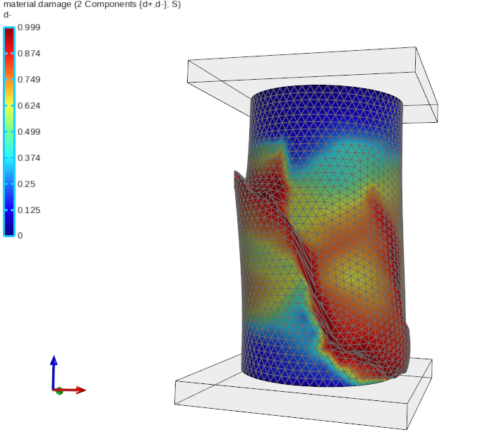
You obtained very ductile curves with that value because this test is (almost) constant strain. It is difficult for a numerical model without imperfections to trigger the localization when the fracture energy is high. Furthermore, you were using the wrong constraints.
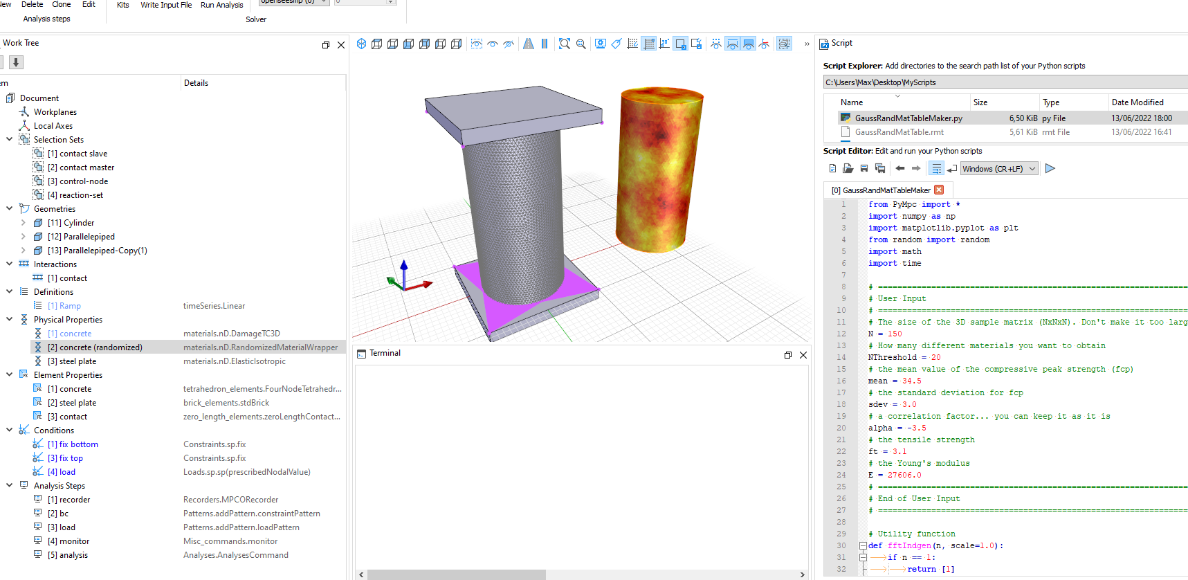
Check the attached model. I used:
- A non-structured tetra mesh, to introduce a bit of imperfection in the mesh
- Steel plates and frictional contacts between the steel plates and the concrete to better simulate the boundary conditions
- Finally I used a Random Material Wrapper to introduce imperfections. I will talk about it in the next webinar about strain localization. But here you can find a preview.
Re: DamageTC3D
Dear STKO teams,
I built two models of reinforced concrete short columns in compression. The first model built two steel plates following your example, but the results did not converge; the second model used node to node links with interaction and finely meshed the steel plates, but the force quickly dropped to 0. Is there a problem with friction contact?
- Attachments
-
- Model 1.rar
- (168.14 KiB) Downloaded 220 times
-
- model 2.rar
- (246.79 KiB) Downloaded 239 times
-
- model 2.png (29.8 KiB) Viewed 4584 times
Re: DamageTC3D
Dear user,
We detected a convergence issue that has been recently improved in the source-code of the ASDEmbeddedNodeElement. It will be released in the new OpenSees version. The compiled new version with this improvement will be released next week by prof. Tarque, together with a new STKO release.
We will keep you up-to-date.
We detected a convergence issue that has been recently improved in the source-code of the ASDEmbeddedNodeElement. It will be released in the new OpenSees version. The compiled new version with this improvement will be released next week by prof. Tarque, together with a new STKO release.
We will keep you up-to-date.
Re: DamageTC3D
Dear user,
you can now download the STKO version 3.1.0
and the latest OpenSees-Solvers from prof. Tarque's website.
It should work fine now
you can now download the STKO version 3.1.0
and the latest OpenSees-Solvers from prof. Tarque's website.
It should work fine now
Re: DamageTC3D
Dear STKO team,
Hello, I have a minor question and hope to get your help. If the tensile strength of concrete is not considered, the ft=Gt=0 in DamageTC3D will not converge. Setting it to a smaller value (for example, ft=0.1, Gt=0.001) still has some influence on the convergence. Is there a recommended value?
Re: DamageTC3D
A concrete has always a tensile strength. It soon tends to zero due to cracking. But it is never exactly zero from the beginning. This is an assumption that is often done with reinforced concrete in beam sections.
Anyway, if you want to simulate it, just use a small ft value, but it will affect the shear strength as well