Page 1 of 1
Plastic Hinges
Posted: Sat Dec 07, 2019 12:38 pm
by Ali shafiee
Hi,
Is there a way to see plastic hinges in elements of a structure after the analysis?
and should we model the structure in "Concentrated Plasticity" to see the plastic hinges or we can see them in a common "Distributed Plasticity"(with Fiber elements) model aswell?
*Thanks in advance*
Re: Plastic Hinges
Posted: Sat Dec 07, 2019 11:27 pm
by MassimoPetracca
When you want to see the progressive formation of plastic hinges, you can simply do a gauss-plot in the post-processor using the curvature as the result. Why? when a plastic hinge appears in a point, the curvature at that point will grow soon, making the particle (gauss-plot) at that point larger then others.
- do your model with either concentrated or distributed plasticity approach
- in the mpco recorder, ask for the proper element result that will give you the curvature (distributed case) or rotation (concentrated case) at the integration points. For example in the distributed case you can choose "section.deformation"
- in post-process do a gauss-plot, and choose one of the 2 curvature components as a result.
Re: Plastic Hinges
Posted: Thu Mar 12, 2020 5:48 pm
by NicolaTarque
I am analyzing a pushover analysis of a 2d frame (3 stories). We have already put the option to see the gauss points at the output.
My question is regarding to visualization of the curvature or rotation. I am using plastic hinges where I enter data of Moment vs Rotation according to Lignos and Krawinkler. That means that my rotation is the curvature times a plastic length (normally 050 of the beam depth).
When I select the option SectionDeformation I can choose also Kappa_Z, but I think it is curvature, right?
Then, if I multiply kappa_Z times 0.5 the bema depth, should I have the same rotation values that i entered in the Lignos and Krawinkler model? I think yes.
Is there any option to see directly Rotation values at a given GP?
Thanks,
Nicola
Re: Plastic Hinges
Posted: Sat Feb 25, 2023 10:43 pm
by Chaymaa
Hello STKO team,
I’m trying to visualize the progressive formation of plastic hinges. My model is a two story masonry building, built using the distributed plasticity approach (Fiber sections). So, as suggested in the previous post, I’m doing the gauss-plot in the post-processor using the curvature as the result. My questions are the following :
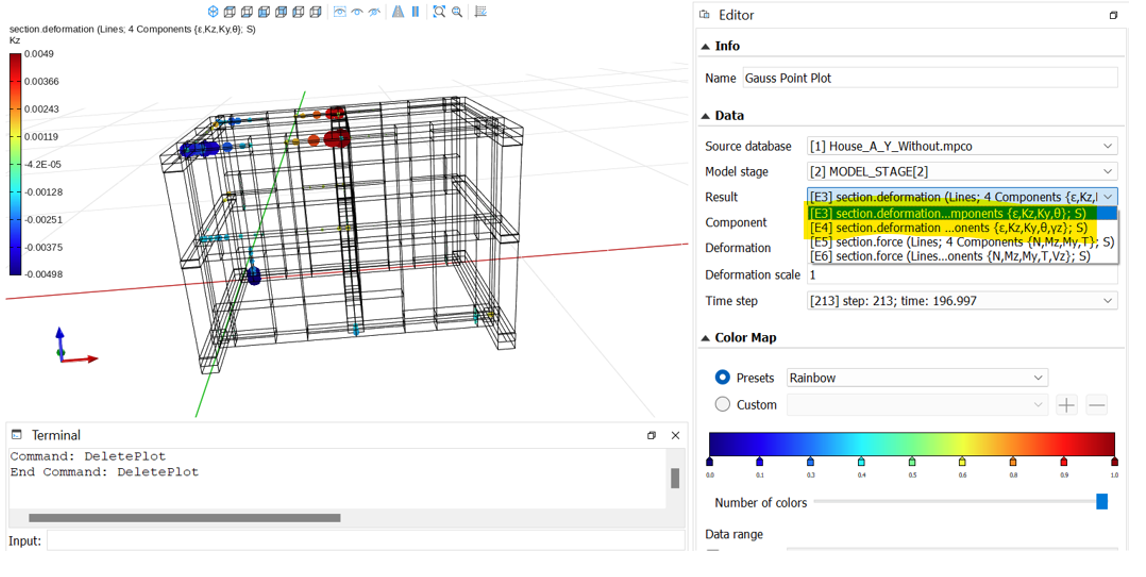
1 – Which result should I use ? E3 or E4 ? And why ?
- k.png (209.64 KiB) Viewed 5045 times
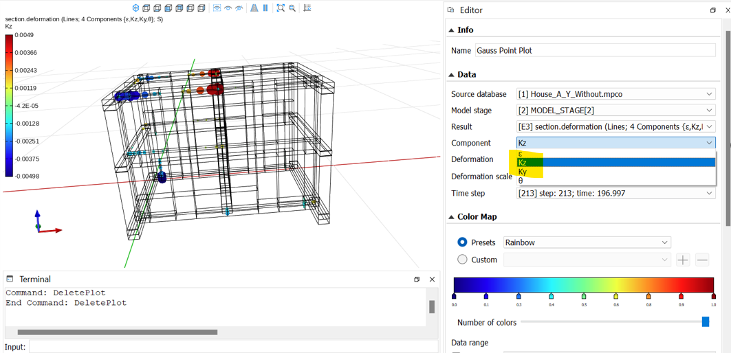
2 – Which component ? ky or kz ? And why ?
- E.png (297.43 KiB) Viewed 5045 times
3 – The results are the same for the piers and the spandrels ? Or the component chose depends on the element ?
P.S: I’m using the Equivalent Frame Modelling approach

- EFM.png (43.36 KiB) Viewed 5045 times
Many thanks in advance!
Re: Plastic Hinges
Posted: Mon Feb 27, 2023 2:43 pm
by STKO Team
1 – Which result should I use ? E3 or E4 ? And why ?
The only difference between E3 and E4 is that E4 has shear deformability along the local Y direction (probably you used a section aggregator), while the E3 does not.
It depends on your model. If you want to visualize results on shear-deformable elements, use E4, otherwise use E3. But you are the only one knowing which element has the shear-deformability.
Which component ? ky or kz ? And why ?
It depends on your local axes. Go in the pre-processor and visualize the local axes, so that you will see what curvature you need.
3 – The results are the same for the piers and the spandrels ? Or the component chose depends on the element ?
This is related to your first question. Piers and spandrels will have the same results if both are shear-deformable (E4) or not (E3). Once again, you are the only one knowing this.
Re: Plastic Hinges
Posted: Tue Feb 28, 2023 3:54 pm
by Chaymaa
Hello STKO team,
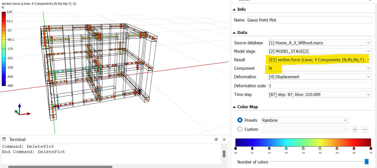
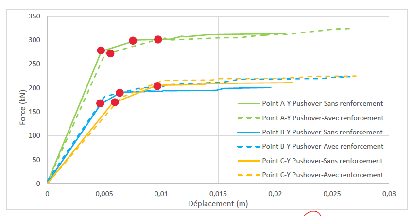
Thank you for your previous response. However, I’m trying in fact to visualize the progressive formation of plastic hinges, in concordance with the force-displacement curve. In that case, will it be more pertinent to see the section.force results (E5 – E6), and what is the difference between the two ? If yes, which component (N or T) ? And why ?
- Capture d’écran 2023-02-28 105315.png (176.57 KiB) Viewed 4981 times
- Capture d’écran 2023-02-28 102518.png (53.42 KiB) Viewed 4981 times
Is there a way to know if the failure is caused by the flexion/shear mechanism ?
Many thanks in advance !
Re: Plastic Hinges
Posted: Wed Mar 01, 2023 9:07 am
by ValentinaSB
Hi Chaymaa,
Chaymaa wrote: ↑Tue Feb 28, 2023 3:54 pm
will it be more pertinent to see the section.force results (E5 – E6), and what is the difference between the two ? If yes, which component (N or T) ? And why ?
To visualize deformations or forces it is up to you. E5 and E6 should be also as E3 and E4 with and without aggregator. N is normal force and T is torsion.
Chaymaa wrote: ↑Tue Feb 28, 2023 3:54 pm
Is there a way to know if the failure is caused by the flexion/shear mechanism?
You need to analyze your results to see if it is a shear or flexural failure.
Best,
Valentina